https://www.lightillusion.com/
Can You Help Me Fix the Error Message I’m Getting with the eeColor LUT Box?
If you’re experiencing issues with the eeColor LUT Box, consulting the eecolor lut box manual can be helpful in troubleshooting. The manual provides step-by-step instructions for fixing error messages and getting the device back to proper functioning. Following the manual’s guidance can save you time and frustration.
Error!
Detect and understand errors using profiling/calibration workflows.
Many problems encountered when calibrating a particular display are often not LightSpace-related problems, but can be difficult to assess if you don’t know what is actually expected and what might be causing the problems.
This page describes possible problems and their probable causes.
LUT calibration and verification issues

The first problem is the calibration of the LUT verification, as this is often difficult to understand, and the results can sometimes indicate that the LightSpace result is not as good as it should be, even if this is not the case.
Since verification is the only way to assess the accuracy of a calibration, it is a critical process that must be fully understood, especially if the reported verification results show that the calibration is inaccurate.
THE CALIBRATION AND VERIFICATION PROCESS
The idea of verifying a calibration by a second profile sequence is obvious and makes perfect sense in simple terms.
After the initial display profiling, Initial Display Set-Up, 3D LUT calibration and hardware integration specific user guides, and generation of the final 3D Calibration LUT, any verification process should demonstrate the accuracy of the calibration that LightSpace has performed….. Especially if the calibration workflow is defined to encompass the entire image path and is not isolated to the display. It should compensate for any signal path errors, right?
Unfortunately, the answer is often no….
Direct HDMI verification
To understand potential verification errors, it is best to first look at the simplest calibration workflow, using a display with internal LUT capability and profiling via a direct HDMI connection from the LightSpace PC.

In a Direct Profiling configuration, the HDMI output of the LightSpace laptop is connected to the HDMI input of the display, enabling direct profiling, as described in the Direct HDMI Profiling section of the Direct Profiling User Guide.
In this profiling workflow, the RGB triplet patch values, as defined by LightSpace, are displayed directly on the monitor via the HDMI connection (assuming there are no active ICC profiles or incorrect graphics card/chip set configurations as defined in the Direct Profiling User Guide) to ensure that the values measured by the probe are as expected and as accurate as the inherent capabilities of the probe.
Based on this direct profiling, the generated 3D calibration LUT will again be as accurate as possible based on the reading accuracy of the probe and the stability of the display.

After LUT generation, the first verification step is to run a Quick Profile with the Active LUT capability within LightSpace.
The Active LUT capability effectively proves the underlying LUT accuracy by passing the patch color data through the LUT before sending the patch to the display via the HDMI connection.
As a result, the patch color displayed will have been ‘corrected’ by the LUT, and the probe will read the new, corrected value, effectively proving the accuracy of the calibration.
The next step is to upload the LUT to the display (as in this example, the display is 3D LUT-enabled) and profile it again.
Ideally, both verification profiles match exactly and the calibration is absolutely accurate.
So, what could be wrong?
In this example, probably very little, since the workflows are very simple, provided that the instructions for managing ICC profiles and graphics card/chipset configurations have been executed correctly.
Even if the active LUT and the actual LUT upload to the display are located elsewhere, the simple RGB signal path minimizes potential problems.
Below you can see the signal and profiling patch for the “Active LUT”.
| Patch generation | Patch generation | Active LUT | HDMI connection | Display measurement | ||||
|---|---|---|---|---|---|---|---|---|
| Patch color defined by LightSpace and sent to the display as HDMI signal | LightSpace Test Patch Generator (TPG) located in front of the LUT. | Active LUT held with LightSpace changes the patch color before it is sent to the display | HDMI connection to the display | Active LUT corrected patch color displayed and measured on the monitor. | ||||
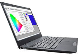 |  |  | 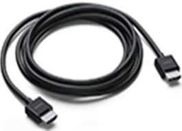 |  |
And the following shows the signal and profile path when the LUT is loaded directly into the display.
| Patch generation | HDMI connection | Patch generation | Active LUT | Display measurement | ||||
|---|---|---|---|---|---|---|---|---|
| Patch color defined by LightSpace and sent to the display as HDMI signal | HDMI connection to the display | LightSpace Test Patch Generator (TPG) located in front of the LUT. | Active LUT held with LightSpace changes the patch color before it is sent to the display | Active LUT corrected patch color displayed and measured on the monitor. | ||||
| | | | |
As you can see, there is little that could go wrong, since the LUT has the same effect on the signal as an Active LUT’, and when it is uploaded to the monitor. And since the signal profiling path is direct and simple, with no potential for distortion, the final calibration of the LUT will be as accurate as possible.
If there are differences between the two verifications that would indicate some sort of variation in the LUT when uploaded to display versus the active LUT held in LightSpace. Such variations could be LUT size (e.g. 17^3 vs. the internal LightSpace 33^3 size), or the need to apply a VideoScale process to the LUT before uploading if the signal path is TV Legal vs. Data Range (Limited vs. Full).
Any “gross” errors where the calibration appears incorrect in some way are likely due to active ICC profiles or VCGT (video card gamma tables) and should be easy to spot as both verifications are incorrect/poor.
Internal TPG calibration and verification
The first real potential for error is that the display has an internal test patch generator (TPG), as it is possible that the internal patch generator could misinterpret the RGB triplet patch values sent by LightSpace. Therefore, the readings recorded by the sonde would not match the correct calibrated values, resulting in inaccurate calibration and verification.
| Patch generation | Data connection | Patch generation | Active LUT | Display measurement | ||||
|---|---|---|---|---|---|---|---|---|
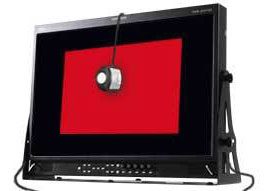
| Patch color defined by LightSpace and sent as RGB triplet values to the display via network/USB connection | USB/network data connection to the display | Internal Test Patch Generator (TPG) located before the LUT. | LUT loaded into the display modifies the RGB triplet color data | LUT corrected patch color displayed and measured via internal display TPG. | ||||
| 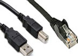 | | | |
The potential for error can arise from the display being YCbCr-based, as with some broadcast monitors, with errors in converting the LightSpace RGB triplet patch values to YCbCr values for the TPG, and also in converting the YCbCr values back to RGB before it passes the calibration LUT (since all 3D LUTs are RGB-based) and is then displayed on the screen (again, since all screens are
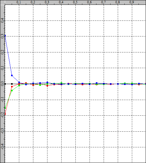
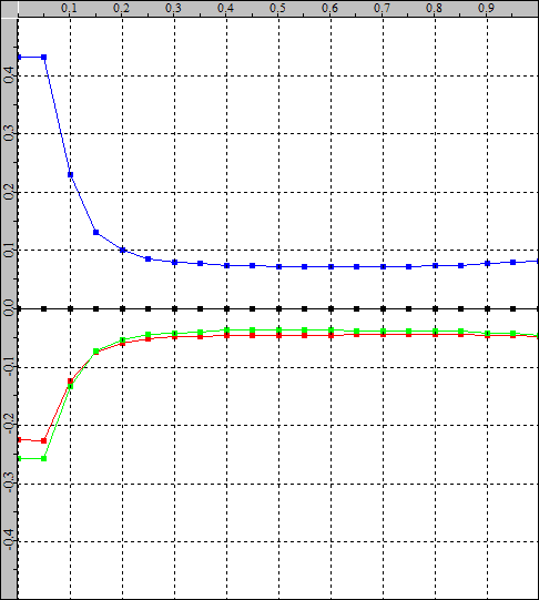
If the conversion from RGB to YCbCr and back to RGB color space is not accurate, the calibration and verification will not be accurate, as can be seen below using RGB balance diagrams to show grayscale variations.
| Native Display – Internal TPG | Active LUT verification | LUT Upload Verification | ||
|---|---|---|---|---|
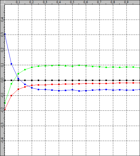 | 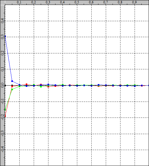 | 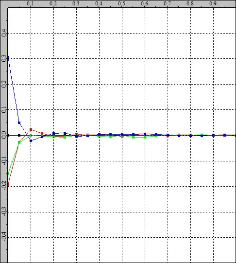 | ||
| The native display shows a large blue contamination in the blacks/shadows, with a predominantly green grayscale. | The Calibration LUT, when verified as Active LUT within LightSpace, shows a reasonable gray level calibration. | If the same LUT is uploaded to the display and verified again, the results will be less accurate. | ||
| Native display – External TPG | Active LUT verification | LUT Upload Verification | ||
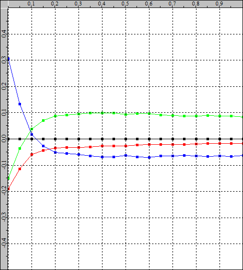 |  | 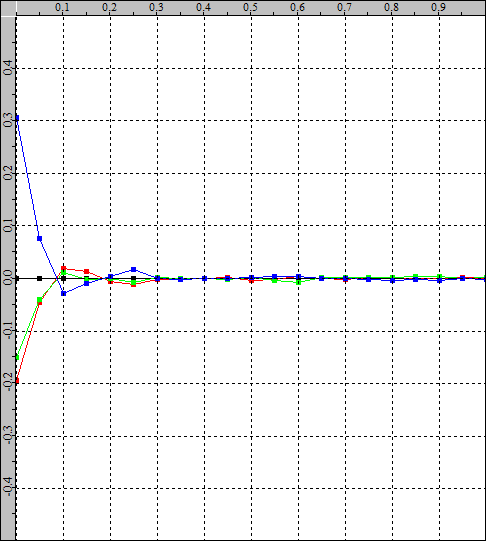 | ||
| When profiling with an external TPG, the native display response is similar to the internal TPG results, but not identical. (Click HERE to see a direct comparison). | The calibration LUT, when verified as an Active LUT within LightSpace, again shows a similar result to the internal TPG, but not identical. | And when the same LUT is uploaded to the display and verified again, the results are again less accurate, but also again different from the internal TPG results.he LUT is uploaded to the display and verified again, the results are again less accurate, but also again different from the internal TPG results. |
What the above errors show is that the signal path processing of this monitor is not optimal, with direct Internal TPG vs. External TPG differences, as well as Active LUT vs. Uploaded LUT variations.
It is also possible that the “error” is reversed when an internal TPG is used to perform the initial profiling and calibration of the LUT generation. This time it’s about the display’s internal signal processing electronics distorting the input video signal.
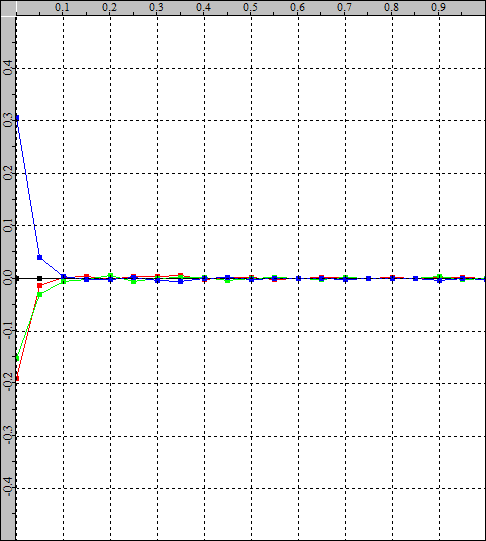
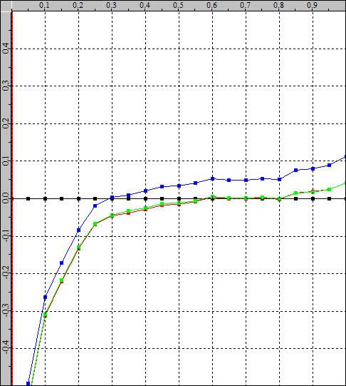
In the following example, the internal TPG was used to profile the display and create a calibration LUT. When the active LUT is held in LightSpace, the calibration appears less accurate than when the same LUT is actually loaded into the display.
| Native Display – Internal TPG | Active LUT verification | LUT Upload Verification | ||
|---|---|---|---|---|
| | | ||
| The original display is profiled with its own internal test patch generator. | Calibration LUT, when verified as Active LUT within LightSpace, has significant errors. | However, when uploading to the display, the calibration results are significantly improved. |
The reasons for the inaccurate verifications are due to the video processing electronics of the display distorting the internal TPG output signal, and when the LUT is held as ‘Active LUT’ within LightSpace, it generates corrected patch values ‘before’ the patch generator and thus does not correctly compensate for the TGP errors.
When the calibration LUT is loaded into the display, it is located after the TGP, correctly compensating for signal path errors after the internal TPG.
Note: For any display, it is really preferable to use an RGB signal path to avoid potential color space conversion issues as well as issues related to 422 color subsampling.g as well as issues related to 422 color subsampling.
LUT size problems
Looking at the above differences between the LightSpace Active LUT and the Uploaded LUT, there is another potential area of error – the actual LUT size.
The default LUT size in LightSpace is 33^3, but when uploaded to a display with internal 3D LUT capability, the size may be different and therefore will show some variation in verification results.
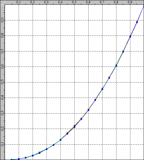
| 33^3 LUT | 17^3 LUT | 5^3 LUT | ||
|---|---|---|---|---|
 | 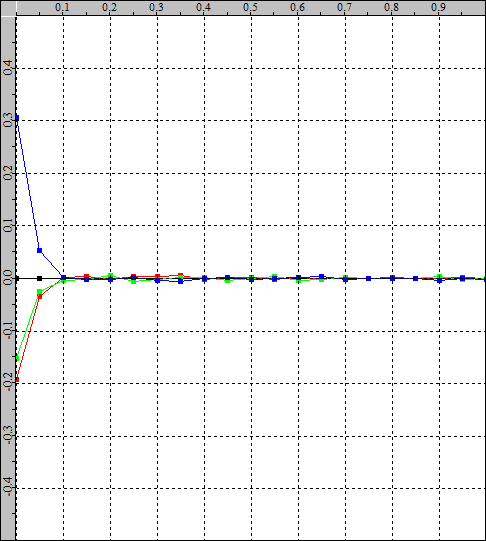 |  | ||
| This is a standard LightSpace 33^3 LUT calibration result…. | 33^3 LUT 17^3 LUT 5^3 LUT This is a standard LightSpace 33^3 LUT calibration result…. This shows the result of using a 17^3 LUT, and the main variation is more blue contamination on the blacks/shadows. And that shows a very small 5^3 LUT, and again the main variation is even more blue contamination on the blacks/shadows. | And that shows a very small 5^3 LUT, and again the main variation is even more blue contamination on the blacks/shadows. |
As can be seen, the likely variation in the final calibration result is mainly in the ability of the LUT to manage the native excessive blue in the black/shadow areas of the display. There are not the same grayscale errors seen in the internal TPG calibration and verification issues mentioned above.
Problems with the signal range
Der erwartete Signalbereich für ein bestimmtes Display – TV Legal vs. Data RangeThe expected signal range for a particular display – TV Legal vs. Data Range – can also lead to calibration errors if the correct range workflow is not applied. – kann auch zu Kalibrierungsfehlern führen, wenn nicht der richtige Bereichs-Workflow angewendet wird.
Problems can arise both in profiling and in the application of the LUT.
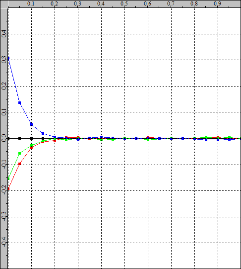
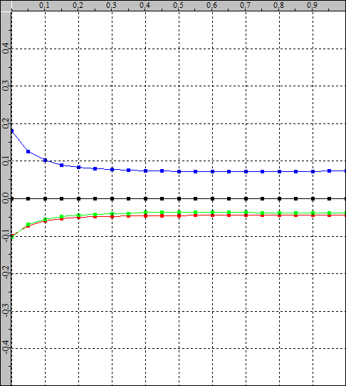
| Correct range – gamma | Correct range – RGB Balance | Correct range – clip | ||
|---|---|---|---|---|
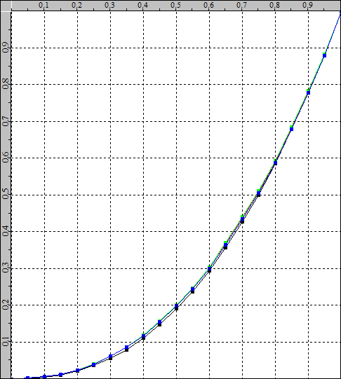 |  |  |
The above diagrams should be used as reference for the following diagrams, not as ideal diagrams.
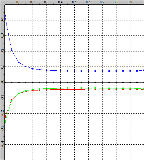
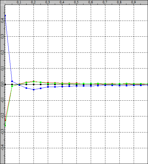
| Incorrect TV Level Range Profiling – Gamma | Incorrect TV Level Range Profiling – Balance | Incorrect TV Level Range Profiling – Clip | ||
|---|---|---|---|---|
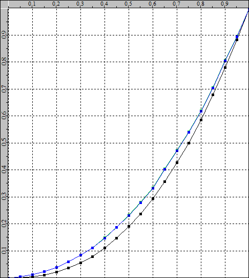 |  |  |
In the above graphs, the display has been profiled with a TV Legal Range signal when the display is expecting a Data Range signal. The gamma graph has shifted up, while the RGB balance shows less blue in the blacks and the clip graph shows a raised profile due to the gamma shift.
The real problem is that the black level has increased and the white level has decreased, resulting in a decrease in the overall contrast level.
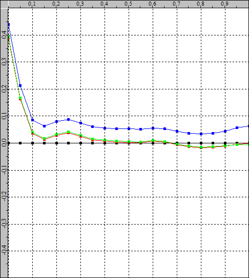
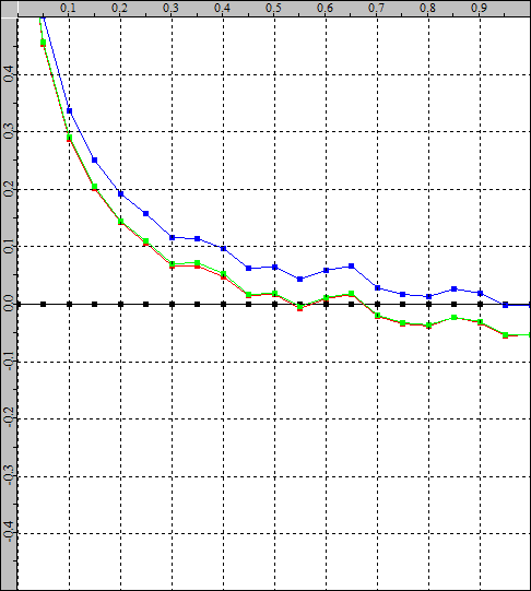
| Incorrect data range profiling – Gamma | Incorrect data range profiling – scale | Incorrect data range profiling – clip | ||
|---|---|---|---|---|
 |  |  |
In the above graphs, the display has been profiled with a data range signal when the display is expecting a TV Legal signal. The gamma graph has shifted downward, while the RGB balance shows a step into black, and the clip graph shows an obvious clipping error as the two lower grayscale levels are identical.
Obviously, any calibration LUT generated with incorrect range profiles will result in an incorrect calibration.
Even if the LUT is generated with the correct range profile, there may be problems when uploading to the display if the LUT is not scaled to the signal path. The most obvious problem is when the 3D LUT inside the display (or LUT box!) uses a full-range cube, but the signal path is TV Legal, which means that the LUT must be scaled to match the TV Legal range using VideoScale.
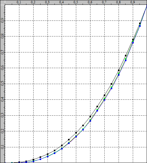
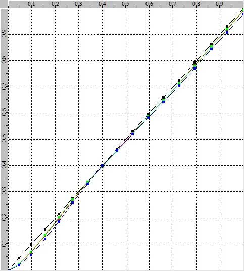
| Incorrect LUT scaling – CIE | Incorrect LUT scaling – Gamma | Incorrect LUT scaling – scale | ||
|---|---|---|---|---|
 |  |  |
The above diagrams show the results of a wrongly scaled LUT, where the LUT is the data range for a TV Legal workflow.
| Correct LUT scaling – CIE | Correct LUT scaling – Gamma | Correct LUT scaling – balance | ||
|---|---|---|---|---|
 |  |  |
The above figures show the correct results when the LUT has been scaled correctly with VideoScale…
Problems with the signal path delay
A very obvious but easily overlooked problem is that of signal delay from the LightSpace PC to the actual display being calibrated, especially if the connection is not a simple direct HDMI connection.
Such a delay means that the patch displayed on the monitor being calibrated actually occurs slightly after the patch displayed in LightSpace. So if the right amount of Extra Delay is not added, the probe will actually start reading before the correct patch is displayed.

Any calibration or verification result is therefore completely wrong and should be easily detectable.
Problems with the signal path
Signal path issues are problems where the display’s internal video processing “distorts” the video signal in unexpected and inaccurate ways, and can even cause major problems if the image path is more complex and uses a number of different hardware components.
For example, the following shows the verification of RGB balance from a display connected to a Resolve system with a BMD Decklink card compared to the same display calibrated via a direct HDMI connection.n a display connected to a Resolve system with a BMD Decklink card compared to the same display calibrated via a direct HDMI connection.
| Native display | Resolve & Decklink Calibration | Direct HDMI calibration | ||
|---|---|---|---|---|
 |  |  | ||
| The native display shows a large blue contamination in the blacks/shadows, with a predominantly warm (red/magenta) grayscale. | When profiling, calibrating and verifying via a Resolve system using a Decklink card, the results are not as expected, with an obvious green/blue error in the shadows. | When the same display is calibrated and verified via a direct HDMI connection to the LightSpace PC, the results improve with near perfect grayscale.The problem is an incorrect RGB to YCbCr conversion in the signal path because the Resolve system was set to YUV, meaning the RGB triplet values from LightSpace were converted to YCbCr in Resolve, and then the YCbCr signal was converted back to RGB within the display. |
Somewhere within these color space conversions there is an error that, while not immediately visible during normal use of the display, becomes very apparent during attempted calibration.
The solution is to set Resolve to RGB444, both with the Resolve system and with the Decklink card, and set the display to explicitly accept the RGB input.
Note: The conversion error can be within Resolve, the Decklink card, the display, or all three…. Without using an external TPG, such as Murideo SIX-G, which can be set to accurately generate YCbCr and RGB patches, it is impossible to define where the problem lies.
It is worth evaluating signal path problems in more detail as they can be the cause of many inaccurate final calibrations, so a more detailed understanding of the workflow of potential problems can help improve understanding.
Profiling before calibration
Using direct HDMI from LightSpace to profile the display to enable generation of a calibration LUT.
| Patch generation | Patch-Generator | HDMI connection | Video editing | Display | ||||
|---|---|---|---|---|---|---|---|---|
| Patch color defined by LightSpace | LightSpace Test Patch Generator (TPG) sends patch via HDMI to display | HDMI RGB connection to the display | Video electronics distort patch color in unexpected/inaccurate ways. | Display and measurement of the patch color on the monitor | ||||
| | |  | |
In the above pre-calibration workflow, the video processing electronics add distortion to the patch color before it reaches the screen (the actual gamut and gamma of the display is irrelevant – only the additional inaccurate processing distortion is important – and this may be within the display or an external video processing system.
As a workflow example, a skin tone patch with triplet value (145, 107, 113) is defined in LightSpace and sent to the display. The video electronics (this could be an external patch generator, LUT box on bypass/zero or within the actual display) distort the triplet values to 146, 105, 114 and it is this triplet value that is then displayed on the screen and the resulting color that is measured by the probe.
When LightSpace generates a calibration LUT, it generates a ‘correction’ within the LUT that corrects the displayed color, including a correction for distortion caused by the video processing electronics.
However, the LUT correction has a different result depending on where in the video path it is added….
If the LUT is positioned before the video processing electronics, it will apply the correction to the generated color before the error is introduced. So the value 145, 107, 113 will be 144, 109, 112, and when this color reaches the video processing electronics, the introduced error will most likely not be the same ‘relative’ error as before, because the color triplet value is NOT the same! The LUT correction will now be wrong because the introduced error will be different….
The LUT must be positioned AFTER the video processing electronics to correct the errors introduced.
FAST PROFILE CALIBRATION NOT ACCURATE
Using a quick profile (gray only or primary only quick profiles are all that is needed) to perform a 3D LUT based calibration can be a very fast and potentially very accurate calibration method.
However, Quick Profile-based calibration only works accurately if the display has a very linear response to changes in the input signal, as well as good RGB separation and potentially good RGB balance.
The problems arise in understanding what the above statement really means….
The first problem is the linearity of the display response to the change in the input signal, i.e. the display on the screen changes by an amount equal to any change in the input signal. For example, changing an input color triplet value to a brighter value, without changing the actual color, will cause a uniform brightness to change only on the screen, without changing the color.
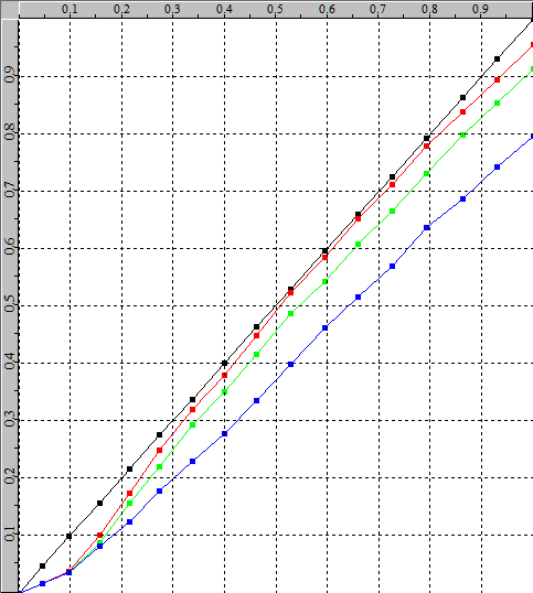
Display response linearity problems can usually be detected with a primary and secondary quick profile as follows.
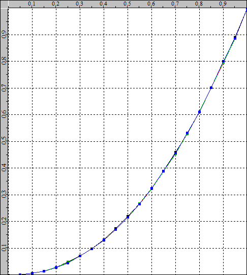
The following left diagram shows an example of a display with a very non-linear response to input signal changes. Using a primary and secondary fast profile, one can see the hue of the measured patches at the edge of the gamut triangle for red, yellow, cyan and magenta, even if the hue is identical for the individual input color patches.
| Non-linear response | Linear desaturation | |
|---|---|---|
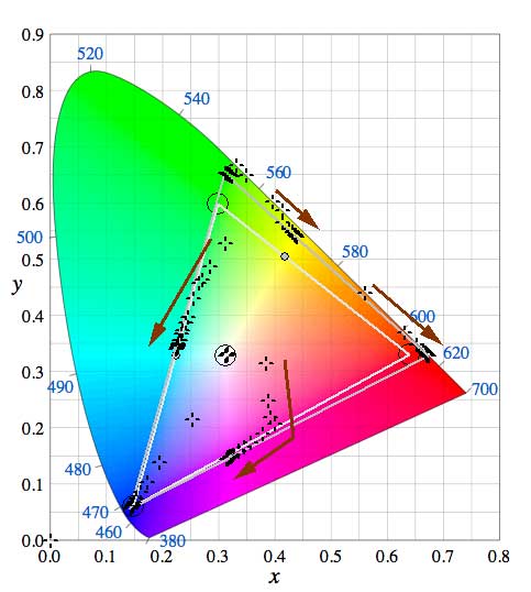 | 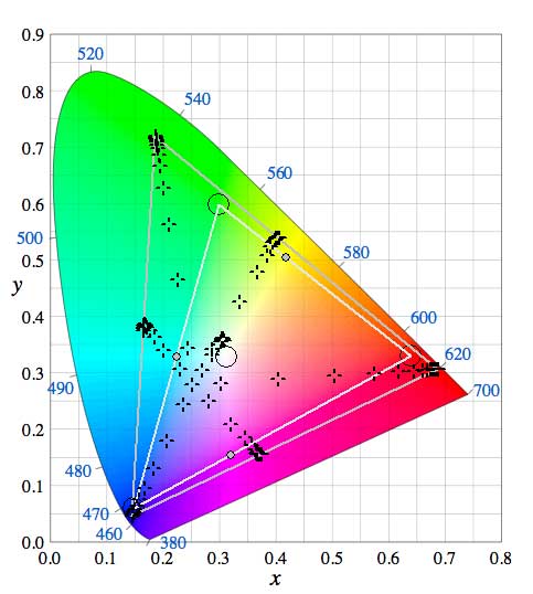 |
The graph on the right shows a response representing linear desaturation of the output color as luma decreases. The measured patches maintain the same relative hue, and they follow the native color temperature of the display backlight. Such a response will not prevent the use of a Quick Profile for LUT generation.
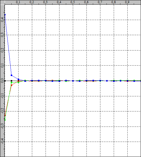
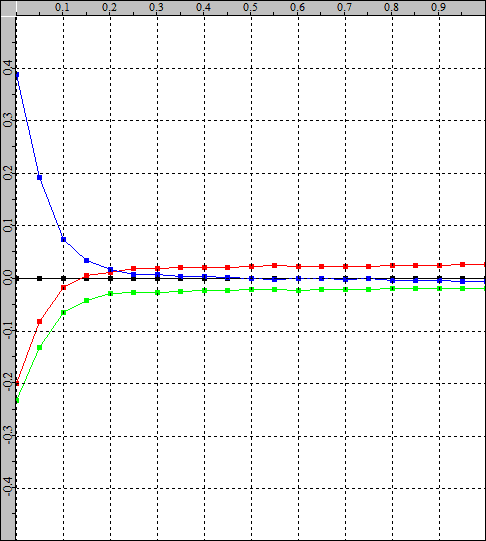
RGB Separation compares each primary R, G, and B patch of the same stimulus value (e.g., Red 128,0,0,0, Green 0,128,0, and Blue 0,0,128) to the equivalent grayscale patch (128,128,128), comparing each RGB patch reading to the expected color matrix combination for the equivalent grayscale patch. Any error in the graph indicates that the display has color decoupling problems with the separate RGB color channels of the display. This means that a change in the input color that should only affect a single color channel will also result in changes within the other color channels – known as cross-coupling between color channels.
| Sensible RGB separation | Poor RGB separation | |
|---|---|---|
 |  |
Channel cross-coupling is an extreme form of nonlinear response to the display, and any display suffering from this condition requires a full volumetric cube profile for accurate calibration.
While the left diagram shows “reasonable” RGB separation, in reality even a display with this response should be calibrated with a cube-shaped profile for the best calibration results.
SOLVE SPECIFIC PROBLEMS
Resolve has a very specific problem when you use the Output/Monitoring LUT capability within the system. The Resolve TPG is located after’ the LUT position, which means that you cannot use the TPG to verify the LUT when it is held within Resolve….
| Patch generation | Network connection | Uploaded LUT | Patch-Generator | Display measurement | ||||
|---|---|---|---|---|---|---|---|---|
| Patch color defined by LightSpace and sent to Resolve as RGB triplet values over the network connection. | Network data connection to Resolve TGP | LUT held in Resolve | Resolve Test Patch Generator (TPG) located AFTER the LUT. | Patch color displayed on the monitor unchanged from the LUT. | ||||
|  | | | |
The only way to overcome this problem and accurately check the LUT when used in Resolve is to use LightSpace’s DIP (Display Independent Profiling) mode and create a “patch set” timeline to play the calibration patches in real time and in sync with LightSpace as all the frames on the timeline pass through the LUT.
Quelle: https://www.lightillusion.com/error.html